Flash Sonoff NSPanel
Video guide through
By: Cables & Coffee
Flash Sonoff NSPanel with our custom firmware
Detailed guide
NSPanel disassembly
Detach the Power block
Make sure to orient the NSPanel the same way as on the picture It has to be oriented so you can read the text naturally. Doing it this way reduce the risk to hurt the bottom diode.

- Place flat screw driver behind this little metal part and lift it up
- Same as previously
Do it softly until you are able to separate the Power block from the rest of the NSPanel.
You should end up with two parts:
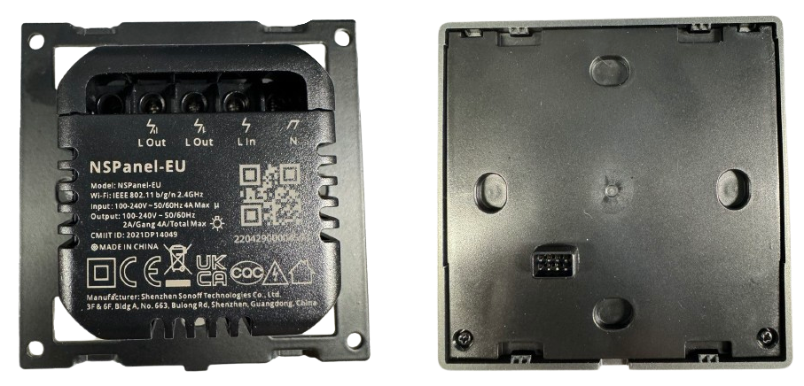
Remove plastic cover from Screen enclosure

- Unscrew it with a cross screwdriver
- Unscrew it with a cross screwdriver
- After that you can detach the plastic cover from the PCB
Now you have two choices, the Lazy way or the Complicated way:
1. Lazy way:
You can flash straight away without detaching the screen from the PCB and remove PCB completely from housing. Important is that you insert the cables and tilt them abit (like in GIF below) so the pins does not come in contact with the metall behind the PCB (risk of short circuiting the USB to TTL). Hold tilted during entire flashing.
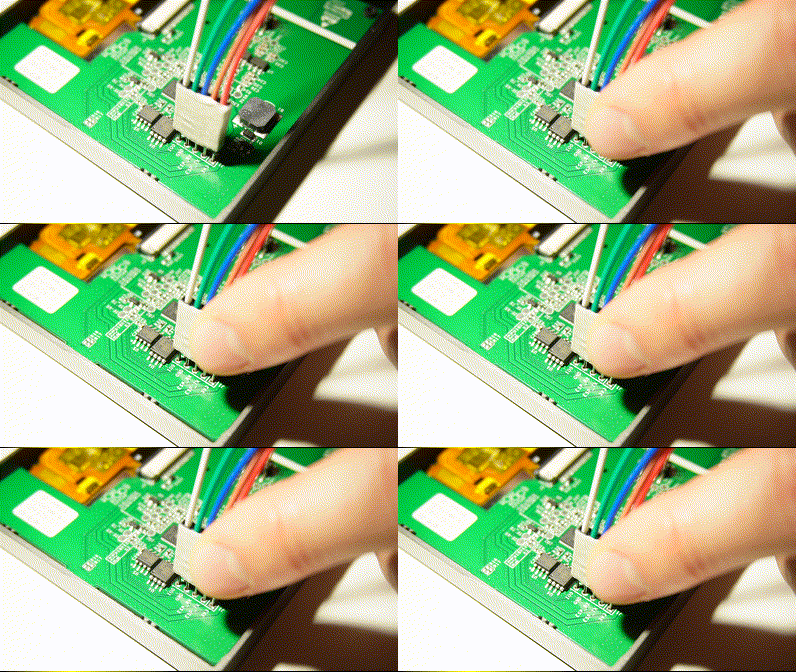
2. Complicated way (detaching screen from PCB and removing PCB from housing):
This operation has to be done very smoothly.

- Push slightly from left to right the black part of the connector (2mm)
- same as point 1.
- Point 1 and 2 unlocked the FFC cable, it can now be slowly taken out from the connector.
The black part of the FFC cable do not contains any electronic nor conductive feature, you can catch it with tweezers without fear to damage it.
Prepare for flashing
In order to get the ESP32 enter in flash mode, GPIO0, noted IO0 on the PCB has to be connected to GND.
Either connect a cable between IO0 and GND (2) as in picture below:

or add an extra cable to Ground pin on USB to TTL as in picture below (white cable):
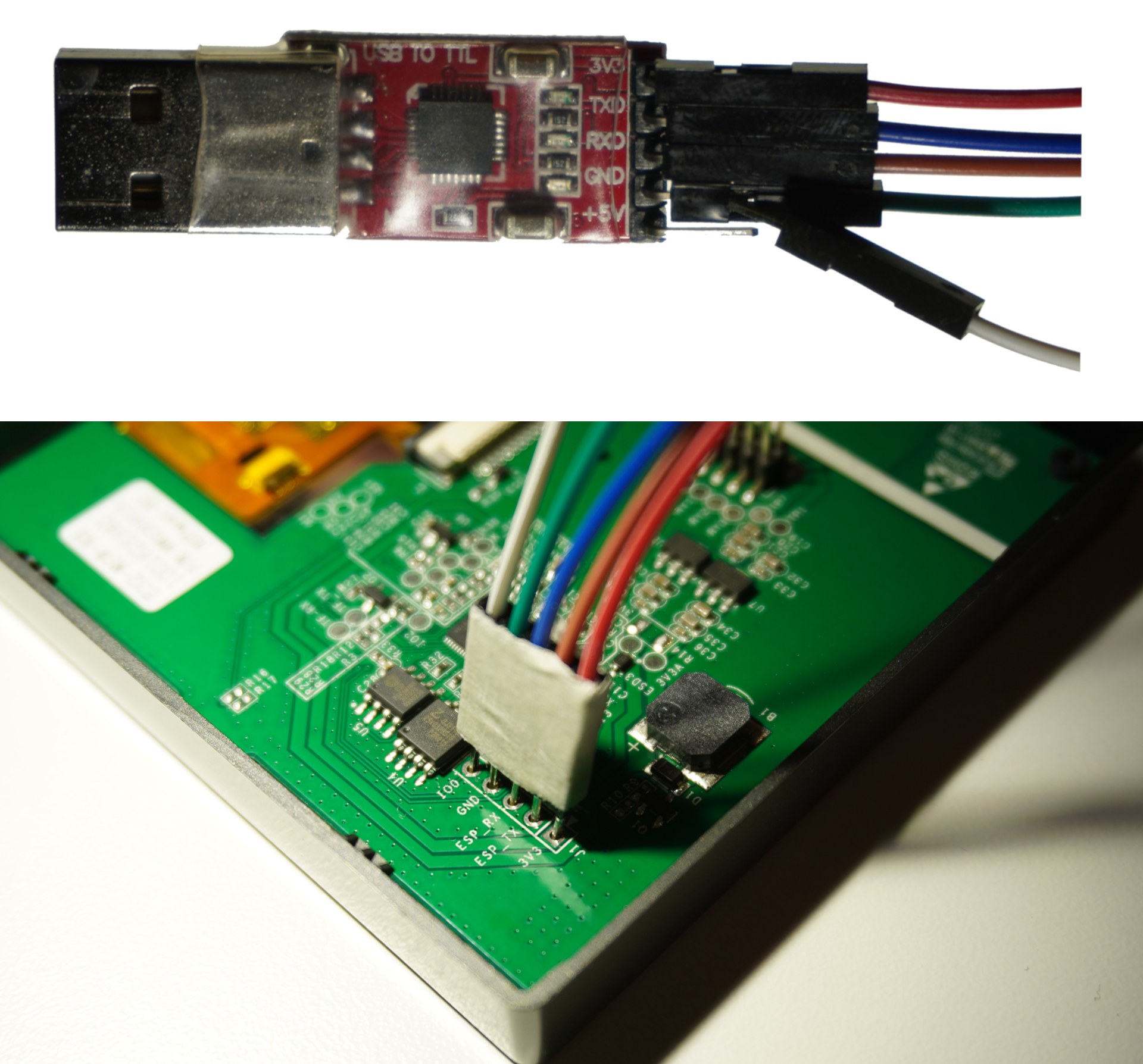
Connect your USB to UART (TTL) converter
Make sure to use the 3v3 (not 5V), this can generally be configured with a Jumper up on the USB to UART converter.
- Connect the USB to UART convert to the PCB:
| USB-UART PIN | NSPanel PCB PIN |
|---|---|
| VCC | VCC (Symbolized by a square on the PCB) |
| RX | TX |
| TX | RX |
| GND | GND |
Notice that RX and TX pins have to be inverted between the devices: it is not TX -> TX, RX -> RX (See upper table).
Flash NSPanel with NSPanelManager custom firmware
First, download the latest firmware merged-flash.bin, either stable or beta.
Then, flash the firmware with your tool of choice:
- ESP Home Web (Chrome or Edge)
- Espressif tool (Windows)
- ESPtool
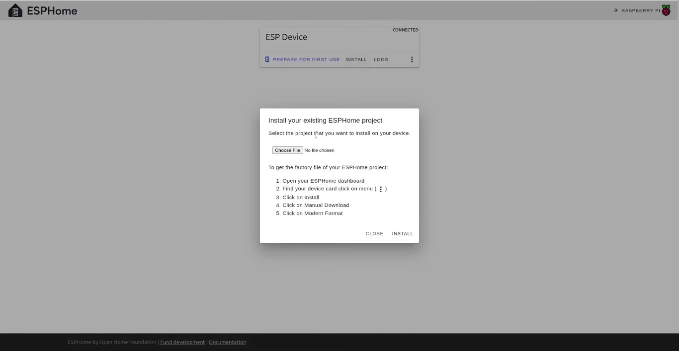
- Go to https://web.esphome.io/ (not supported in Firefox)
- Connect USB to TTL to computer
- Press Connect (choose correct USB device)
- Press Install
- Press Choose file...
- Choose .bin file to flash
- Press Install
- Wait for flashing to complete
-
Download Espressif tool from here: https://www.espressif.com/en/support/download/other-tools
-
Open the tool and choose to flash an
ESP32 chip. -
Click on the
...button and select the firmware you downloaded at step 1 calledmerged-flash.bin. -
enter
0x0as the upload address. -
Check the first checkbox next to the firmware file
-
Click the
STARTbutton and wait until it writesFINISH.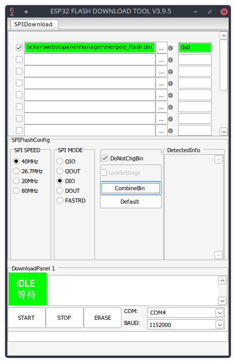
- Open a terminal.
- Navigate to the directory where you saved the
merged_flash.bin-file. - To determine if you have selected the right port, run
esptool.py flash_id --port <port>. You will have to replace<port>with the actual port connected to the NSPanel. This will do a check and see if the tool can communicate with the NSPanel. - Run
esptool.py --baud 921600 --port /dev/ttyUSB0 write_flash 0x0 merged_flash.bin. You will have to replace/dev/ttyUSB0with the actual port connected to the NSPanel.
On Windows it might be just esptool without the .py at the end.
On Windows /dev/ttyUSB0 will have to be replaced by something like COM4. If using MacOS or Linux the
port will be something similar to /dev/ttyUSB0.
After the flash of the firmware, you will not see any visible change on the NSPanel display this is normal at this stage.
You are now ready to (configure your flashed Sonoff NSPanel)[./configure-flashed-nspanel.md].